10:
This post is about how to implement a vector field generated by Perlin noise directly on the GPU using GLSL. If you want, you can regard this as the step 0 before implementing fluid simulations with shaders. I have written elsewhere here about vector fields, and how to implement them on the CPU, but let’s recall the idea, and in particular the concept of a “lookup table”. Namely, in our case a lookup table is a two-dimensional array which encodes the vector field: you can imagine a grid with coordinates (i,j), such that to each of its cells a 2-dimensional vector is attached. The motion of a given particle in the vector field is obtained by displacing the particle in the cell (i,j) via the value of the lookup table at the given cell. To represent it on the screen, we compute the new position of the particle, and draw there. This seemingly redundant comment will be relevant later, just wait.
Okay, the procedure above is easy-peasy, if we want to move pixels, we just define a grid as big as the whole screen, so that the cell (i,j) will correspond to the pixel at position (i,j) indeed; we do the computations above, and go home. Boom! Ehm, no, not really. The point is that if you tried to do just that, the iteration over all the pixels in the screen would take so long that you would get barely a frame or two every couple of seconds (probably less). Sorry, about that.
Enter shaders! We can indeed use the GPU to perform all these calculations via a custom made fragment shader. First, we need to sort out how to send the information contained in the lookup table to the shader. Since the table is nothing else than a two-dimensional array, we can write the value of the field directly in a texture. On modern graphic cards, textures are very quick to upload, and we can upload more than one. Wait a minute, aren’t textures supposed to be used for… colors and stuff? Yes, but. A texture is nothing else that a carrier for data: more precisely, at each of its coordinate, it contains the value of red, green, blue and alpha which will be combined to provide the color for the pixel at the given coordinate. We can then use two of the color channels to provide the x and y component of a vector. In this case, I have chosen a unit vector field, i.e. at each point the vector is specified just by an angle, given by the value of Perlin noise at the given coordinate. This datum is written on the blue channel of the ofImage field in the code, from which we will obtain a texture. Another texture will contain the pixels we want to displace: I will refer to it as the “ink” texture. Finally to update the ink texture we will use a “ping-pong technique”, about which I have written here.
Now that we have sorted out a slick way to send data to the GPU, we have to deal with the elephant in the room. As I commented earlier, the CPU algorithm is based on the fact that we calculate the new position of the particle at (x,y) by obtaining the value of the vector field at the very same position, move the particle, and draw something (a circle, a pixel, etc.) “there”. Unfortunately, the fragment shader does not allow to “move” fragments, since everything it knows is the given fragment! This is encapsulated in my favourite motto concerning shaders “It is a lonely world, no one talks to no one else here!”: this means that everything we know about a vertex or a fragment can’t be shared. 
Luckily, there is a way out, and it comes courtesy of textures. A texture can indeed be “looked up” from any fragment: so, instead of moving the particle, we trace back its motion. In other words, if we are at the fragment in position p, instead of saying “go to the fragment p + field(p) and draw my color”, we say “the color at p is the color of the ink texture at p-field(p)”. There is an explanation why this is a sensible idea, and it has to do with (partial) differential equations, and their (local) flows.
We can now look at the code in openFrameworks, where I have added some mouse interactivity for fun. Notice you need to provide an image to start with.
ofMain.cpp
#include "ofMain.h"
#include "ofApp.h"
//========================================================================
int main( ){
ofGLFWWindowSettings settings;
settings.setGLVersion(3, 2); //we define the OpenGL version we want to use
settings.setSize(1024, 680);
ofCreateWindow(settings);
// this kicks off the running of my app
ofRunApp(new ofApp());
}
ofApp.h
#pragma once
#include "ofMain.h"
class ofApp : public ofBaseApp{
public:
void setup();
void update();
void draw();
ofImage field;
ofImage ink;
ofImage photo;
ofTexture inkTex;
ofTexture fieldTex;
ofShader shader;
ofFbo fbo;
ofFbo main;
float t = 0;
float mouse_x;
float mouse_y;
void keyPressed(int key);
void keyReleased(int key);
void mouseMoved(int x, int y );
void mouseDragged(int x, int y, int button);
void mousePressed(int x, int y, int button);
void mouseReleased(int x, int y, int button);
void mouseEntered(int x, int y);
void mouseExited(int x, int y);
void windowResized(int w, int h);
void dragEvent(ofDragInfo dragInfo);
void gotMessage(ofMessage msg);
};
ofApp.cpp
#include "ofApp.h"
//--------------------------------------------------------------
void ofApp::setup(){
ofBackground(0);
ofHideCursor();
ofToggleFullscreen();
//Allocating images and textures
ink.allocate(ofGetWidth(), ofGetHeight(), OF_IMAGE_COLOR);
field.allocate(ofGetWidth(), ofGetHeight(), OF_IMAGE_COLOR);
fbo.allocate(ofGetWidth(), ofGetHeight(), GL_RGB);
main.allocate(ofGetWidth(), ofGetHeight(), GL_RGB);
//Setting up the lookup table
ofPixels pix = field.getPixelsRef();
for (float x = 0; x < ofGetWidth(); x++) {
for (float y = 0; y < ofGetHeight(); y++) {
float st = ofNoise(x * 0.0001, y * 0.0001);
pix.setColor(x, y, ofColor(0.0, 0.0, st * 2.0 ));
}
}
field.update();
ink.update();
fieldTex = field.getTexture();
photo.load(path_to_image);
photo.resize(ofGetWidth(), ofGetHeight());
inkTex = photo.getTexture();
main.begin();
photo.draw(0, 0);
main.end();
shader.load("shader.vert", "shader.frag");
}
//--------------------------------------------------------------
void ofApp::update(){
if (t < 2) {
t += 0.001;
}
mouse_x = (ofGetMouseX() - mouse_x) * 0.1;
mouse_y = (ofGetMouseY() - mouse_y) * 0.1;
}
//--------------------------------------------------------------
void ofApp::draw(){
fbo.begin();
shader.begin();
shader.setUniformTexture("tex0", main.getTexture(), 0);
shader.setUniformTexture("tex1", fieldTex, 1);
shader.setUniform1f("windowWidth", ofGetWidth());
shader.setUniform1f("windowHeight", ofGetHeight());
shader.setUniform1f("mx", mouse_x/ ofGetWidth());
shader.setUniform1f("my", mouse_y /ofGetHeight() );
shader.setUniform1f("t", t);
main.draw(0, 0);
shader.end();
fbo.end();
swap(fbo, main);
fbo.draw(0, 0);
}
//--------------------------------------------------------------
void ofApp::mousePressed(int x, int y, int button){
main.begin();
ofSetColor(ofRandom(0.0, 255.0), ofRandom(0.0, 255.0), ofRandom(0.0, 255.0));
ofDrawCircle(ofGetMouseX(), ofGetMouseY(), 30, 30);
main.end();
}
Here are is the vertex shader
shader.vert
#version 150
uniform mat4 modelViewMatrix;
uniform mat4 projectionMatrix;
uniform mat4 textureMatrix;
uniform mat4 modelViewProjectionMatrix;
in vec4 position;
in vec4 color;
in vec4 normal;
in vec2 texcoord;
out vec2 varyingtexcoord;
uniform sampler2DRect tex0;
void main()
{
varyingtexcoord = texcoord.xy;
gl_Position = modelViewProjectionMatrix * position;
}
and the fragment shader
shader.frag
#version 150
// this is how we obtain the textures
uniform sampler2DRect tex0;
uniform sampler2DRect tex1;
in vec2 varyingtexcoord;
uniform float mx;
uniform float my;
uniform float windowWidth;
uniform float windowHeight;
uniform float t;
out vec4 outputColor;
void main()
{
float x = gl_FragCoord.x / windowWidth;
float y = gl_FragCoord.y / windowHeight;
float l = sqrt((x - mx) * (x - mx) + (y - my) * (y - my) ) * t;
vec2 xy = vec2(cos( ((texture(tex1, varyingtexcoord).z) + mx) * 2 * 3.14), sin(((texture(tex1, varyingtexcoord).z) + my) * 2 * 3.14));
outputColor = texture(tex0, (varyingtexcoord - l * xy) );
}
It looks like this
A better result can be obtained by interpolating on the output color, but I was lazy. 
Why did I mention that this is step 0 in understanding how to implement a fluid simulation (like smoke, dust, etc.) on the GPU? This is related to the fact that the vector field in this case is *fixed*, i.e. it is an external vector field. In a fluid, the velocity field is a solution to the Navier-Stokes equations which can be exactly solved for very few cases, and it is “advected”, i.e. you have to imagine that it gets transported itself by the fluid. A nice article on these topics can be found here: if you get comfortable with the basic concepts in this post, you will able to follow it, modulo probably some of the maths.
Nowadays there are tons of libraries to do fluid simulations, like for instance ofxFluids, ofxFlowTools, etc. Why bother, then? I could say because understanding things is always better, but the truth is I do not have the answer to this question: you will have to find your own.
08:
Reaction-Diffusion algorithms are very fascinating, since they are capable of producing incredibly organic patterns. They can also be computationally expensive if the grid of choice is fine enough. In a nutshell, we regard every pixel of an image as a cell containing two types of chemicals in different proportions, and whose combination produces a given color on the screen. The “diffusion equation” is such that, as time goes on, the proportion of the two chemicals changes according to that of the neighborhood cells. Since the algorithm is pixel* based, at its finest, we might think this is a job for a fragment shader. And that’s indeed the case! We have to be careful though concerning two aspects. First, the algorithm uses information about the adjacent pixels, and we know that a fragment shader only treats fragment by fragment information, it does not allow sharing among fragments. This is solved by using a texture to store information about the chemicals. This brings us to the second point: we need to store the previous state of the chemical proportions to compute the next one. On the other hand, a shader is not “persistent”, in the sense that all the information it has concerning fragments is lost on the next frame. Enter FBO and ping-pong technique! Framebuffer objects allows what is called “off-screen rendering”. In other words, instead of rendering the pixels directly to screen, they are rendered to a buffer, and only later displayed to the screen. Hence, we can pass the FBO as a texture to the shader, use, say, the red and green values of the texture at the given fragment coordinate as our chemicals percentage, and set the color of the fragment using the new values of the percentages. This technique is usually referred to as “ping-pong technique”, because we go back and forth from the buffer to the screen. It is particularly useful for modelling particle systems directly on the GPU. In Processing, a FBO is an object described by the class PGraphics, and the shader becomes a method that can be sent to the object.
Here’s the code
PGraphics pong;
PShader diff;
void setup(){
size(800, 800, P2D);
pong = createGraphics(width, height, P2D);
diff = loadShader("diffFrag.glsl");
pong.beginDraw();
pong.background(255, 0, 0);
pong.endDraw();
diff.set("u", 1.0/width);
diff.set("v", 1.0/height);
pong.beginDraw();
pong.noStroke();
pong.fill(0, 255, 0);
pong.ellipse(width/2, height/2, 10, 10);
pong.endDraw();
}
void draw(){
pong.beginDraw();
pong.shader(diff);
pong.image(pong, 0, 0);
pong.resetShader();
pong.endDraw();
image(pong, 0, 0);
}
//// diffFrag.glsl
varying vec4 vertColor;
varying vec4 vertTexCoord;
uniform float u;
uniform float v;
uniform sampler2D texture;
float laplaceA(in vec2 p, in float u, in float v){
float A = 0.05 * texture2D(texture, vertTexCoord.st + vec2(-u,-v))[0] + 0.2 * texture2D(texture, vertTexCoord.st + vec2(0,- v))[0] + 0.05 * texture2D(texture, vertTexCoord.st + vec2(u,-v))[0] +
0.2 * texture2D(texture, vertTexCoord.st + vec2(-u,0))[0] - 1.0 * texture2D(texture, vertTexCoord.st + vec2(0,0))[0] + 0.2 * texture2D(texture, vertTexCoord.st + vec2(u, 0))[0] +
0.05 * texture2D(texture, vertTexCoord.st + vec2(-u,v))[0] + 0.2 * texture2D(texture, vertTexCoord.st + vec2(0,v))[0] + 0.05 * texture2D(texture, vertTexCoord.st + vec2(u,v))[0];
return A;
}
float laplaceB(in vec2 p, in float u, in float v){
float B = 0.05 * texture2D(texture, vertTexCoord.st + vec2(-u,-v))[1] + 0.2 * texture2D(texture, vertTexCoord.st + vec2(0,- v))[1] + 0.05 * texture2D(texture, vertTexCoord.st + vec2(u,-v))[1] +
0.2 * texture2D(texture, vertTexCoord.st + vec2(-u,0))[1] -1.0 * texture2D(texture, vertTexCoord.st + vec2(0,0))[1] + 0.2 * texture2D(texture, vertTexCoord.st + vec2(u, 0))[1] +
0.05 * texture2D(texture, vertTexCoord.st + vec2(-u,v))[1] + 0.2 * texture2D(texture, vertTexCoord.st + vec2(0,v))[1] + 0.05 * texture2D(texture, vertTexCoord.st + vec2(u,v))[1];
return B;
}
void main(){
float A = texture2D(texture, vertTexCoord.st )[0] ;
float B = texture2D(texture, vertTexCoord.st )[1] ;
float A_1 = A + (0.9 * laplaceA(vertTexCoord.st, u , v) - A * B * B + 0.0545 * (1 - A)) ;
float B_1 = B + ( 0.18 * laplaceB(vertTexCoord.st, u, v) + A * B * B - (0.062 + 0.0545) * B) ;
gl_FragColor = vec4(A_1, B_1, 1.0, 1.0);
}
And here is an example:
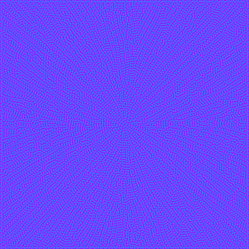
Tip: try to change the numerical values in the definition of A_1 and B_1 in the fragment shader code.
*: A fragment shader technically deals with fragments rather than pixels.
11:
It’s been a while since the last post. I have been busy with (finally!) starting to set up a website to collect some of my works, and I’ve been more or less finishing a couple of interactive installations. For this reason, interactivity and real-time processing have captured my attention recently. It turns out that when you want to interact with a piece of code which produces graphics, and as soon as what you are doing involves more than just a couple of pairs of colored circles, you run quickly into performance issues. So, unless you are one of those digital artists drawing a blinking white circle in the middle of the screen and call it art (it’s fine, don’t worry, go on with it), you need to find your way around these types of issues. In practice, this amounts to get comfortable with words like Vertex Buffer Object, C++, and shaders, to which this post is dedicated.
The story goes like this: modern graphic cards (GPU) have a language they use, called GLSL . For instance, when in Processing you draw a line or a circle, what is actually happening behind the curtains is a communication between the CPU and the graphic card: Processing informs the GPU about the vertices of the line, the fact that it has to be line, the color of the vertices, etc. There are several stages from when the vertices are comunicated to the final result that you see on your screen. Some of these stages are user programmable, and the little programs that take care of each of these stages are called “shaders”. Shaders are notoriously difficult to work with: you have to program them in C, basically, and they are quite unforgiving with respect to errors in the code. On the other hand, they are really really fast. If you want to know why it is so, and how a (fragment) shader operates, give a look here.
So, why the hell would you want to learn such a tool? Well, if you, like me, are fond of glitch art, you must have realized that interactive real-time glitch art is almost impossible if you try to work pixel by pixel: even at a resolution of 800×600, the amount of computations for the CPU to get a framerate of 30fps is impractical. Enter fragment shaders! If you delegate the work to the GPU, it becomes more than doable.
I can’t go into the detail of the code I present in the following, but there are very good tutorials on the web that slowly teach you how to tame shaders. In particular, give a look here. Rest assured: you really need to be programming friendly, and have a lot of patience to work with shaders!
PImage img;
PShader glitch;
void setup(){
size(800, 600, P2D);
background(0);
img = loadImage(insert_link_to_image);
img.resize(800, 600);
glitch = loadShader("glitchFrag.glsl");
glitch.set("iResolution", new PVector(800., 600., 0.0) );
}
}
void draw(){
glitch.set("iGlobalTime", random(0, 60.0));
if (random(0.0, 1.0) < 0.4){
shader(glitch);
}
image(img, 0, 0);
resetShader();
}
---------------
// glitchFrag.glsl
#ifdef GL_ES
precision mediump float;
precision mediump int;
#endif
#define PROCESSING_TEXTURE_SHADER
varying vec4 vertTexCoord;
uniform sampler2D texture;
uniform vec3 iResolution;
uniform float iGlobalTime;
float rand(vec2 co){
return fract(cos(dot(co.xy ,vec2(12.9898,78.233))) * 43758.5453);
}
void main(){
vec3 uv = vec3(0.0);
vec2 uv2 = vec2(0.0);
vec2 nuv = gl_FragCoord.xy / iResolution.xy;
vec3 texColor = vec3(0.0);
if (rand(vec2(iGlobalTime)) < 0.7){
texColor = texture2D(texture, vertTexCoord.st).rgb;
}
else{
texColor = texture2D(texture, nuv * vec2(rand(vec2(iGlobalTime)), rand(vec2(iGlobalTime * 0.99)))).rgb;
}
float r = rand(vec2(iGlobalTime * 0.001));
float r2 = rand(vec2(iGlobalTime * 0.1));
if (nuv.y > rand(vec2(r2)) && nuv.y < r2 + rand(vec2(0.05 * iGlobalTime))){
if (r < rand(vec2(iGlobalTime * 0.01))){
if ((texColor.b + texColor.g + texColor.b)/3.0 < r * rand(vec2(0.4, 0.5)) * 2.0){
uv.r -= sin(nuv.x * r * 0.1 * iGlobalTime ) * r * 7000.;
uv.g += sin(vertTexCoord.y * vertTexCoord.x/2 * 0.006 * iGlobalTime) * r * 10 *rand(vec2(iGlobalTime * 0.1)) ;
uv.b -= sin(nuv.y * nuv.x * 0.5 * iGlobalTime) * sin(nuv.y * nuv.x * 0.1) * r * 20. ;
uv2 += vec2(sin(nuv.x * r * 0.1 * iGlobalTime ) * r );
}
}
}
texColor = texture2D(texture, vertTexCoord.st + uv2).rgb;
texColor += uv;
gl_FragColor = vec4(texColor, 1.0);
}
In the following, you can see the result applied to a famous painting by Caravaggio (yes, I love Caravaggio): it matches real time framerate.
If you want to apply the shader to the webcam, you just need to set up a Capture object, called, say, cam, and substitute img with cam in the Processing code. Enjoy some glitching!
Glitch Shader from kimri on Vimeo.
